Speakon Conversions
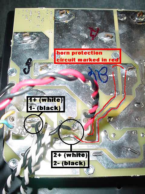
This is a picture of an SP1G crossover circuit board.
I used speakon CH1 for the lows, and CH2 for the highs.
The low input goes directly to the woofer,
as seen where the yellow and blue wires connect.
The high input connects where the horn protection circuit starts.
The 2- wire is common for both the horn's "-" and the protection circuit's "-".
The red wire plugged in to the circuit board goes to the horn's "+" terminal.
The 2+ wire is soldered to a point just below the honrn's wire connectors,
and shown in this picture is the protection circuit traced with a red line,
showing how the "+" side gets to the horn's connector.
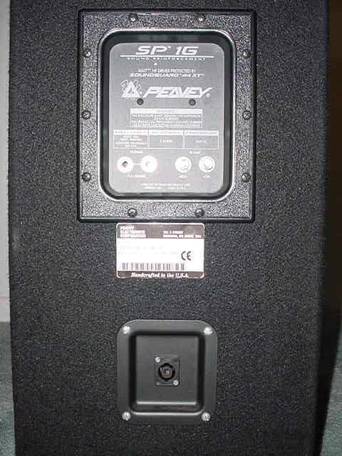
This is the back side of the speaker shown put back together.
A rectangular hole was cut out in order for the recessed speakon jack plate
to mount on the speaker.
The Bi-Amp High and Low 1/4" input jacks have plugs inserted in them
in order to open their switches and bypass the crossover circuitry when using
the speakon jack (speakon jack is wired for bi-amp only).
DO NOT USE THE SPEAKON INPUT WITHOUT THESE PLUGS!
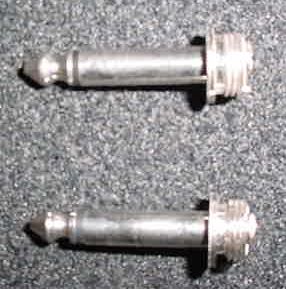
These are the plugs inserted in the Bi-Amp inputs.
They are standard speaker cable ends with the back sides
cut off, so they just barely stick out of the back of the speaker.
Since they won't be carying any power and are only to open the switching jacks,
these are the cheapest plugs that Radio Shack carries.
If the speaker is to be used full range (normal input) at any time,
then remove the plugs and plug in a standard 1/4" speaker cable to either
of the "normal" inputs (and do not connect anything to the speakon jack).
Bi-amping is also still possible with 1/4" cables in the Bi-Amp inputs
and not using the speakon jacks.
Also, although this is not recomended, a bi-amp setup with the speakon jack in use,
could daisy chain off the 1/4" Bi-Amp inputs to another speaker
instead of just using the blank plugs.
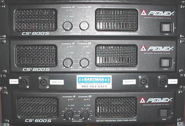
This is the front of one of my amp racks.
The far outside speakon jacks are for the SP118 subs.
Only 1+ and 1- are used at this time, but 2+ and 2- could also be
wired in parallel with 1+ and 1- to provide extra current carying capacity.
Inside the SP118 sub, speakon CH1 and CH2 would also have to be wired parallel
to eachother, both going to the driver. If an SP218 were used,
then CH1 would go to one driver, and CH2 would go to the other driver.
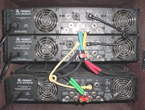
The X-1 crossover module is installed in the middle amp.
Low output goes to Ch. A input on the lower amp (yellow cable)
This amp is in bridge mode providing 1,200 watts divided between two SP118 subs
The middle amp is in bridge mode, and the internal default connection of the
X-1 module is the mid frequencies to Ch. A input.
This amp is also in bridge mode providing 1,200 watts
divided between the woofers of two SP1G speakers
The high output of the X-1 module connects to Ch. A input of the top amp (black cable)
This amp is in stereo mode. (Ch. B is currently used for monitors)
This provides 400 watts divided between the horns of two SP1G speakers.
If monitors are not used, or another amp is dedicated to monitors, then the top amp's
Ch. A "thru" jack can connect to Ch. B input.
This will allow 240 watts per horn (one on each channel)
instead of 200 watts each (sharing 400 watts on one channel).
In the picture...
the Green tipped wires go to "Sub" connector CH1
the Red tipped wires go to "Mid/Hi" connector CH1
the Yellow tipped wires go to "Mid/Hi" connector CH2
The Blue tipped wires go to "Sub" connector CH2, but are actually unused at this time.
Soon, I will double them up with the Green tipped wires
and change my SP118 subs to use both channels.